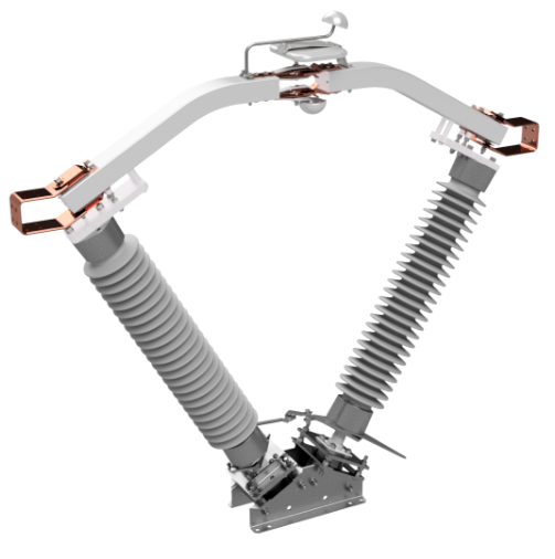
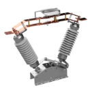
The CB-AV incorporates the same quality features as those designed into the parallel insulator CB-A.
The switch can be used in a substation or it can be mounted phase-over-phase in a transmission line application.
The CB-AV switch ships with the pole units fully assembled with insulators. The CB-AV also can be shipped as a “Quick Install” unitized switch with the three phases mounted to a common base and completely adjusted.
Quality Construction
The CB-AV continues the Cleaveland/Price tradition of designing simple, dependable switches without the use of castings. Knowledge gained from working with customers to identify and solve general switch problems has played a major part in refining the CB-AV. Significant design features include:
Total non-cast aluminum, copper, and steel parts resulting in superior dependability
Live parts constructed from extruded aluminum and hard-drawn, high-conductivity copper, producing stronger, more conductive components than parts made of cast materials
Silver-to-silver, high-pressure line contacts for effective transfer current
Magnetically attracting parallel path hinge and jaw contacts for outstanding performance under short circuit
Wiping action at both the jaw contacts and hinge contacts that keep the contacts clean for years of reliable service. Jaw contacts have a long contact wipe surface to accommodate insulator movement.
Tin-plated copper terminal pads that can accept terminal connectors on three surfaces
Aluminum to tin-plated copper bolted connections. All bolted contact surfaces are prepared and treated with an oxide inhibitor. Moving contacts are silver-to-silver with a hard-drawn, high-conductivity copper base material.
Special hinge design supports high cantilever terminal loads while maintaining low pivot force
By the Numbers (Ratings)
CB-AV
Voltage Ratings
Amperage Ratings
Catalog
Number
Nominal
Voltage (kV)
Maximum
Voltage (kV)
BIL (kV)
Insulator
TR No.
Continuous
Current (A)
Peak Withstand
Current (kA)
Short-Time Withstand
Current (kA @ 3 sec.)
CVFB
69
72.5
350
216
1200
99
38
CVFC
69
72.5
350
216
1600
114
44
CVFD
69
72.5
350
216
2000
164
63
CVFF
69
72.5
350
216
3000
195
75
CVGB
115
123
550
286
1200
99
38
CVGC
115
123
550
286
1600
114
44
CVGD
115
123
550
286
2000
164
63
CVGF
115
123
550
286
3000
195
75
CVHB
138
145
650
288
1200
99
38
CVHC
138
145
650
288
1600
114
44
CVHD
138
145
650
288
2000
164
63
CVHF
138
145
650
288
3000
195
75
CVJB
161
170
750
291
1200
99
38
CVJC
161
170
750
291
1600
114
44
CVJD
161
170
750
291
2000
164
63
CVJF
161
170
750
291
3000
195
75
Center Break
Superior Reliability through Design
Our center break switch line is a non-cast, braidless design for superior reliability.